Back to home
http://www.keithl.com/ncharge.html
My N-Charge series 1 laptop battery no longer charges. Too bad, it cost $300 15 months ago, and has already been in for replacement once. The warranty is over, and Valence Technology can't fix them. Can I fix it, or is it scrap? Lets see...
DISCLAIMER: Lithium Ion batteries are EXPLOSIVE. Be afraid. Be VERY afraid. Do not short them out or put holes in them, or you will KILL yourself and BURN DOWN YOUR HOUSE. You have been warned. Now, back to the takeapart.
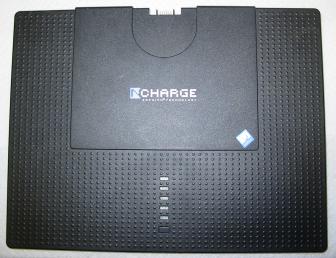
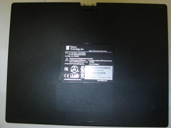
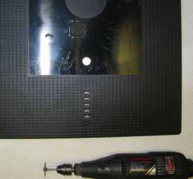
Here's a picture of the unit, front and back:
|
|
|
| Front | Back |
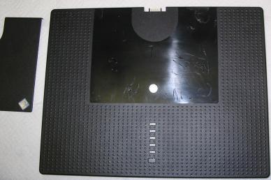
Hmm, no obvious screw holes. But there might be something under the front cover or the bottom label. These both are glued on and peel off:
|
|
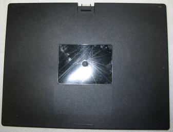
| Front Cover | Back Cover |
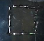
Nope. Everything appears to be glued together. Time to get destructive. If we cut plastic only under the front cover, then we can cover the hole with the front cover later. Note, this must be done very carefully!. Lithium Ion batteries are explosive; put a hole in one and it can put a hole in you! Lets cut a square inch hole:
|
|
|
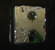
| Cut hole | Cut hole detail | Plastic removed |
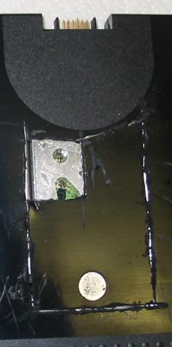
Everything is stickytaped together, but we can peel off the plastic cover. We can see a metal cover over the circuit board, and the edge of the top left battery. No access to components, though! Let's get a little more aggressive; let's cut away everything between the batteries that is still covered by the front cover:
|
|
|
| Cut second hole | Remove plastic | Try a third hole |
I've got a bad feeling about this. It looks like the metal cover extends from top to bottom edges, and there is no way to pull just the cover and work on the circuit board. Time to get drastic. It looks like the plastic cover is welded all the way around the edge of the unit. This sucker is welded shut! So, let's take the Dremel cutting tool all the way around the outside edge. After much cutting and gnashing of teeth, we can peel away the front and back covers of the whole battery:
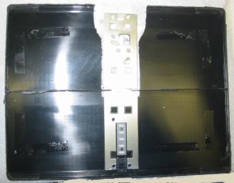
|
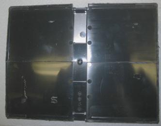
|
| Inside of front cover | Inside of back cover |
Note the ridge of plastic running across the center of the front cover; I had to dig a bit with the Dremel tool to get at it.
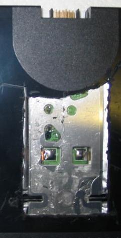
The guts of the N-Charge unit are revealed in their full glory. Note, you can get a preview of these if you watch the TV screen of the X-Ray machine as you go through the airport. If I manage to repair this unit and take it through the Xray, it will be full of so many kludges and repairs that I will probably get arrested for carrying a bomb, sigh.
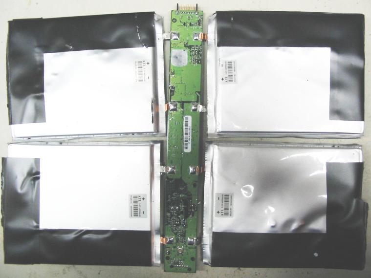
There are actually 8 cells; each battery is two flat cells in parallel, each about 3mm thick. The battery terminals are soldered to the board, which runs from top to bottom. The pushbotton is the round silver thing with the yellow center, near the bottom of the circuit board. The green LEDs are tiny surface mount squares above it. Note, the LEDs still light up at this stage. However, the battery terminals are quite fragile, and I broke some off, sigh.
Each battery is labeled 3.2V and 4950 mA-hr. That is 126.7 Watt-hours. I measured the batteries, and the voltages were 3.21V, 3.20V, 3.28V, and 3.28V.
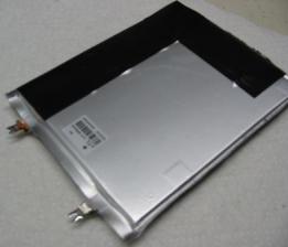
|
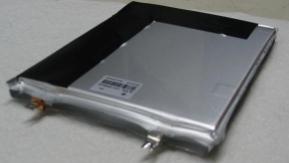
|
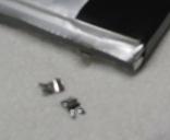
|
| Battery | Edge view | Battery with broken terminal |
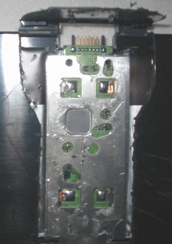
Here are some pictures of the circuit board, after I unsoldered the batteries:
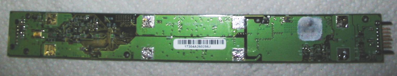
Front of the circuit board
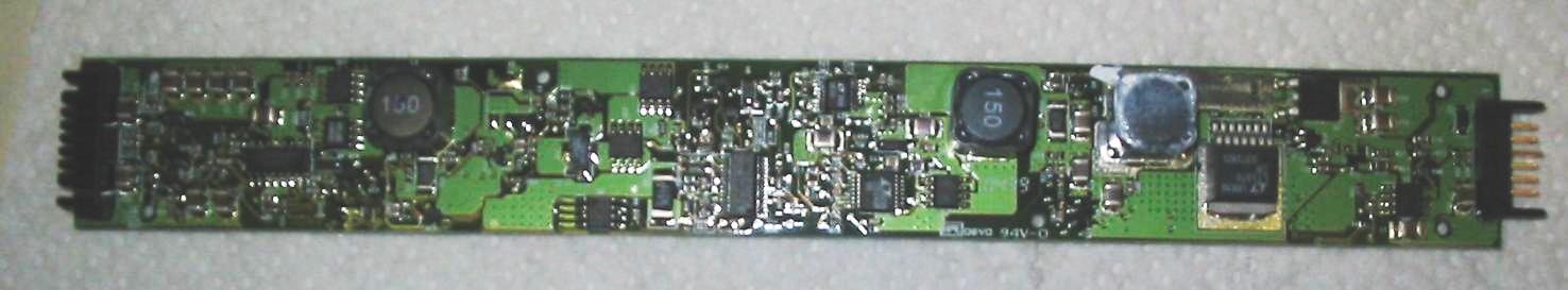
Back of the circuit board
Quite a complicated board, actually. They need a custom IC for this ... Everything is surface mount, with components on both sides. The back side has most of the components on it. There are three large two-terminal inductors, the left (L3) and middle (L2) inductors marked "150", and the right inductor (L1) marked "4R7". To the right of inductors is a Linear Technologies LT1370 high efficiency switching regulator. This is at the laptop output end of the board, so it is probably in charge of producing power (efficiently!) from the batteries to the laptop. My guess is that they are less worried about efficiency for charging the batteries.
The middle of the board appears to be the battery charger. The big IC in the middle is a Texas Instruments (?) bq2060a battery gas gauge. Near it is an LTC1435 and an LTC1621? Left of that is a Microchips 24LC02B 2kbit I2C eprom.
| There are quite a few "4407 BD4U2Y" 8pin SOIC transistors, but I don't know what they are or who makes them. This is the logo: |
| That may be an Anachip 4407 30V 11A PFet. |
The left end of the board has the accessory charger connector. The accessory charger is controlled by an LTC1266C.
That is all I have time to figure out right now. I will get back to this unit later. I've ordered a replacement. :-/
Back to home
last revision July 1, 2005